why choose us
Quality Assurance
OPTICO has passed ISO9001-2015/CE/CPR/ROHS/FCC certification and have reliability test reports from 3rd party lab.
Strong Production Capacity
OPTICO has developed its total production area to 20,000 square meters, and has 400 production and testing equipments.
Professional Team
OPTICO team will respond you within 12 hours to provide the most suitable rather than the most expensive solutions.
Responsibility
With OPTICO scientific quality monitoring and warehouse tracking system, it solves every unexpected problem honestly and quickly.
What is Coupler
In optical fiber communication, a coupler is a device used to split or combine light signals in different fiber optic paths. It allows the transmission of optical signals between multiple fibers, enabling the distribution of signals to multiple devices or the combination of signals from different sources onto a single fiber. A coupler typically consists of two or more input ports and one or more output ports. The input ports receive the incoming optical signals, which are then split or combined according to the coupler's design. The output ports distribute the split signals to different fibers or combine the signals onto a single fiber.


Advantages of PLC Splitter


Small & Space-Saving Design
PLC splitters are perfect for usage in confined spaces and congested telecommunication cabinets because of their small size and space-efficient construction. Network operators may optimize space use with their tiny form factor, resulting in more efficient and well-organized network deployments.
Elevated Division Ratio
The capacity of PLC splitters to produce large splitting ratios — that is, to divide optical signals into many pathways without compromising signal quality — is one of its noteworthy features. PLC splitters provide flexibility for a range of network topologies and deployment circumstances by supporting split ratios as high as 1:2, 1:4, 1:8, and even higher.
Minimal Insertion Loss
To guarantee dependable data transfer in telecommunications, signal strength maintenance is essential. Because PM Fiber Splitter has a low insertion loss, they divide optical signals with the least amount of signal attenuation possible. This feature aids in maintaining signal integrity and overall network performance.
The capacity to use broadband
PLC splitters may function across a large range of wavelengths because of their exceptional broadband capacity. Because of their adaptability, they can be used with a wide range of optical systems, thus network operators may deploy them in a variety of applications without having to take wavelength specificity into account.
Dependability and Sturdiness
Reliability in telecommunications is critical. PLC splitters are made with premium materials and manufacturing techniques, which provide strong and long-lasting parts. Because of its dependability, there is less need for regular maintenance and less downtime due to constant performance throughout time.
The ability to scale
Scalability becomes an important factor as network requirements change. Because Polarization Maintaining Splitter are scalable, network operators may easily add more splitters to their systems to meet the increasing need for data transmission capacity.
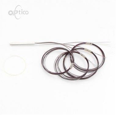
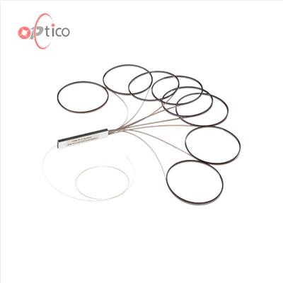
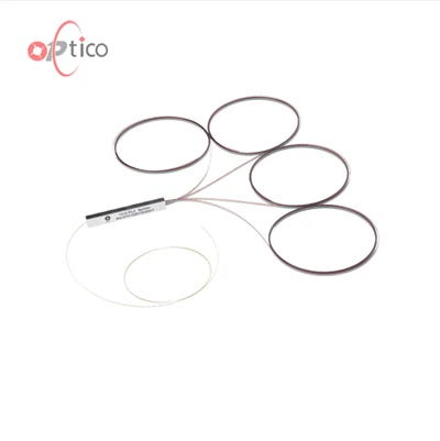
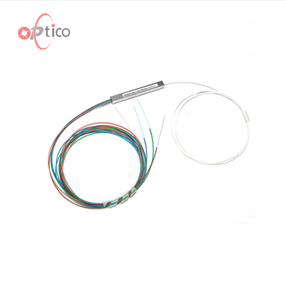
Bare Fiber PLC Splitter
A bare fiber PLC splitter has no connectors at the bare fiber ends and is suitable for PON networks that can be installed in the pigtail cassette, test instrument, and WDM system, which minimizes space occupation. It is relatively fragile on fiber protection and needs a complete protection design on carrying box body and device.
Blockless Fiber PLC Splitter
The Blockless PLC Splitter has 900um loose tube fiber protection on the input and output fibers and can be provided with a selection of connectors at fiber termination, making it suitable for use directly in distribution boxes or network cabinets.
Fanout PLC Splitter
Fanout PLC splitter is mainly used for 0.9mm optical fiber , where the ribbon fiber can be converted to 0.9mm optical fiber through fan-out. Fiber adapters can be provided both for the input and output ends of this type of splitter. It can be used directly to meet the low demand for the size of the splitter.
ABS Box PLC Splitter
The ABS box PLC splitter has a plastic ABS case and provides good protection for inner optical components and cables. It is designed for convenient and reliable installation, but its volume is relatively large. ABS box PLC splitter is widely used with outdoor fiber distribution boxes for PON, FTTH, FTTX, and GOPN networks and network cabinets.
Tray PLC Splitter
Tray PLC splitter uses a space-saving package to better cable management and signal transmission. Tray PLC splitter can accommodate a variety of PLC Splitter with various types of connectors: SC/PC, SC/APC, FC/PC, FC/APC, ST/PC, ST/APC, LC/PC, LC/APC, etc.
Rack- Mount PLC Splitter
Rack-mount PLC Splitter is packaged in a 19-inch rack-mount panel. It provides excellent optical performance and convenient network installation and is widely used in FTTH, PON, EPON, GPON, CATV, and data centers.
LGX Box PLC Splitter
LGX Box PLC splitter has a strong metal box to house the PLC splitters. It can be used alone or easily installed in a standard fiber optic patch panel or fiber optic enclosure. The standard LGX metal box enclosure provides a plug-and-play method for integration into the network, which eliminates any risk during installation.
Mini plug-in Insert Type PLC Splitter
A mini plug-in insert type PLC splitter is designed for plug-and-play splitter applications and provides reliable protection for the fiber optic splitter. It is usually installed in the wall-mount FTTH box for fiber optic signal distribution.
Application of PLC Splitter
Data Center
PLC splitters are frequently used in data center networks to distribute fast data to numerous servers and storage devices. This makes it possible for data centers to efficiently handle high volumes of data traffic, resulting in quick and seamless data transfer.
Optical Access Networks
PLC splitters are frequently used in optical access networks to provide high-speed internet connectivity to a number of clients. They provide end users with high-speed and dependable connectivity and are perfect for FTTH (Fiber to the Home) and FTTB (Fiber to the Building) applications.
Passive Optical Networks (PONs)
PLC splitters are a crucial component of passive optical networks (PONs), which are optical networks that link numerous consumers to a single optical fiber. Each customer has a unique dedicated connection thanks to the PLC splitter's separation of the optical signal into various pathways.
Medical Equipment
To distribute the optical signals from various cameras to a single monitor, PLC splitters are also used in medical equipment such as endoscopes. Because of this, medical experts can view photos from different perspectives and get a better understanding of the internal structure of the patient's body.

In passive optical networks (PON), a PLC splitter is widely installed between the PON Optical Line Terminal (OLT) and the Optical Network Terminals/Units (ONTs/ONUs) that the OLT serves. The single fiber link coming from the Central Office (CO) OLT is connected with the input of a splitter and is split into a given number of fibers leaving the splitter. The number of outputs in the PLC module determines the number of splits.
PLC splitters can be used in centralized PON architecture or distributed architecture. In a centralized PON architecture, a 1x32 PLC splitter is often used in the Central Office. In a distributed PON architecture, a 1x4 PLC splitter is firstly directly connected to an OLT port in the Central Office, then each of the four fibers is routed to an outside plant terminal/enclosure box that houses a 1x8/1x4 PLC splitter.
FBT Splitter vs PLC Splitter: What Are the Differences?
Operating Wavelength
FBT splitter only supports three wavelengths: 850nm, 1310nm, and 1550nm, which makes its inability to work on other wavelengths. The PLC splitter can support wavelengths from 1260 to 1650nm. The adjustable range of wavelength makes PLC splitter suitable for more applications.
Splitting Ratio
Splitting ratio is decided by the inputs and outputs of an optical cable splitter. The maximum split ratio of FBT splitter is up to 1:32, which means one or two inputs can be split into an output maximum of 32 fibers at a time. However, the split ratio of PLC splitter is up to 1:64 - one or two inputs with an output maximum of 64 fibers. Besides, FBT splitter is customizable, and the special types are 1:3, 1:7, 1:11, etc. But PLC splitter is non-customizable, and it has only standard versions like 1:2, 1:4, 1:8, 1:16, 1:32, and so on.
Splitting Uniformity
The signal processed by FBT splitters cannot be split evenly due to a lack of management of the signals, so its transmission distance can be affected. However, PLC splitter can support equal splitter ratios for all branches, which can ensure a more stable optical transmission.
Failure Rate
FBT splitter is typically used for networks requiring the splitter configuration of less than 4 splits. The larger the split, the greater the failure rate. When its splitting ratio is larger than 1:8, more errors will occur and cause a higher failure rate. Thus, FBT splitter is more restricted to the number of splits in one coupling. But the failure rate of PLC splitter is much smaller.
Temperature-Dependent Loss
In certain areas, the temperature can be a crucial factor that affects the insertion loss of optical components. FBT splitter can work stable under the temperature of -5 to 75℃. PLC splitter can work at a wider temperature range of -40 to 85 ℃, providing relatively good performance in the areas of extreme climate.
Price
Owing to the complicated manufacturing technology of PLC splitter, its cost is generally higher than the FBT splitter. If your application is simple and short of funds, FBT splitter can provides a cost-effective solution. Nevertheless, the price gap between the two splitter types is narrowing as the demand for PLC splitters continues to rise.
Size
FBT splitters typically have a larger and bulkier design compared to PLC splitters. They demand more space and are better suited for applications where size is not a limiting factor. PLC splitters boast a compact form factor, making them easily integrable into small packages. They excel in applications with limited space, including inside patch panels or optical network terminals.
PLC Splitter Manufacturing Technology
Substrate Preparation
The manufacturing process begins with the preparation of a substrate, which is typically made of silica glass. This substrate will serve as the foundation for the waveguide circuits.
Photolithography
Photolithography is a crucial step in creating the waveguide circuits. A photosensitive material is applied to the substrate, and a photomask with the desired circuit pattern is placed over it. Ultraviolet light is then used to transfer the pattern onto the photosensitive material. This process defines the layout of the waveguides on the substrate.
Etching
After the photolithography step, the substrate undergoes etching to remove the material not protected by the pattern. This creates the actual waveguide structures on the substrate. Wet or dry etching techniques may be employed, depending on the specific requirements of the design.
Deposition of Waveguide Layers
Additional layers may be deposited on the substrate to enhance the performance of the waveguides. These layers can include materials with specific refractive indices to optimize signal propagation.
Waveguide Formation
The deposited layers are then patterned to form the actual waveguide structures. This step ensures that the optical signals are guided along the desired paths with minimal loss.
Splitter Design and Fabrication
The design of the splitter configuration (1x2, 1x4, etc.) is integrated into the waveguide pattern. The splitting ratio is determined during this stage of the manufacturing process. The lengths and shapes of the waveguides are precisely calculated to achieve the desired splitting characteristics.
Assembly and Packaging
Once the waveguide circuits are fabricated, the PLC splitter chip is assembled and packaged. This involves connecting the input and output fibers to the waveguide circuits. Packaging is essential to protect the delicate components from environmental factors and to ensure consistent and reliable performance.
Testing and Quality Control
PLC splitters undergo rigorous testing to ensure that they meet specified performance criteria. This includes testing for insertion loss, return loss, uniformity of splitting, and other key parameters. Quality control measures are implemented throughout the manufacturing process to identify and address any defects or deviations from the design specifications.
Final Inspection and Calibration
Before the PLC splitters are released for commercial use, a final inspection is conducted. This includes calibration to guarantee that the actual performance matches the intended design.
Coupler Loss and Performance Evaluation in Optical Fiber Networks
A coupler in optical fiber refers to a device that allows the splitting or combining of light signals in optical fiber networks. It is an essential component used for various applications such as signal distribution, power monitoring, and wavelength division multiplexing (WDM) systems.
Couplers are designed using different technologies, including fused biconical taper (FBT) couplers, planar lightwave circuit (PLC) couplers, and fiber Bragg grating (FBG) couplers. FBT couplers are made by heating and stretching two fibers together, causing them to fuse and create a taper region. PLC couplers are fabricated using lithography and etching techniques on a silica substrate, allowing for precise control of the coupling ratio. FBG couplers use fiber gratings to reflect specific wavelengths, enabling selective coupling of light signals.
Coupler loss refers to the power loss that occurs when light is split or combined in a coupler. It is a critical parameter in optical fiber networks as it directly affects the overall system performance. The performance evaluation of couplers involves measuring their insertion loss, excess loss, uniformity, and directivity.
The latest point of view in coupler research focuses on improving their performance characteristics. Researchers are exploring novel design techniques to reduce the insertion loss and excess loss of couplers, as well as enhance their uniformity and directivity. Additionally, there is a growing interest in developing couplers for advanced applications such as mode-division multiplexing (MDM) and space-division multiplexing (SDM) systems, which require efficient and low-loss coupling of multiple modes or spatial channels.
Applications of Fiber Optic Couplers

Telecommunications
Fiber optic couplers connect fiber ends to transmit data over long distances with benefits like scalability, interference resistance, and enhanced security. Recent advancements in nanotechnology extend their applications to acoustic nanotube transflectors and carbon-coated Nanomembranes for water purification.

Data centers
Fiber optic couplers support the diverse network infrastructure needed for data storage, processing, and internet connectivity. These couplers use fiber optic cables to reduce transmission losses and provide higher bandwidths, crucial for rapidly transmitting large digital files.

Cable TV networks
Cable TV networks use fiber optic couplers for high-speed connectivity. These couplers, like 1x2 and 2x2 singlemode types, transmit signals over longer distances with minimal loss. WDM tap couplers divide bandwidths by wavelengths, maximizing fiber use for increased traffic. Variable ratio fiber couplers, alongside components like Receive Wavelength Demultiplexer, correct power imbalances, connecting amplifier source nodes to downstream facilities for efficient signal reception.
International Certificates


Shenzhen OPTICO Communication Co., Ltd was established in April, 2008. Over the next 13 years, OPTICO expanded and increased its production because of the contracts with many EU Telecom Companies. OPTICO's main products fields including Indoor/Outdoor Fiber Cable, Data Center Fiber Patch cord, PLC Splitter, CWDM/DWDM/AWG/FWDM, SFP transceiver, and Media converter. All of products have passed CE, FCC, ROHS, ISO, ROHS certifications.
FAQ
We're professional plc splitter and coupler manufacturers and suppliers in China, specialized in providing high quality customized service. We warmly welcome you to buy high-grade plc splitter and coupler in stock here from our factory. Contact us for more details.
fiber optic splitter 1x16, monomode multimode